
- لطفا گزینههای محصول را انتخاب کنید پی ال سی لوگو LOGO 8 SIEMENS.


نقد و بررسی : Analog Input Module 6ES7134-6JD00-0CA1
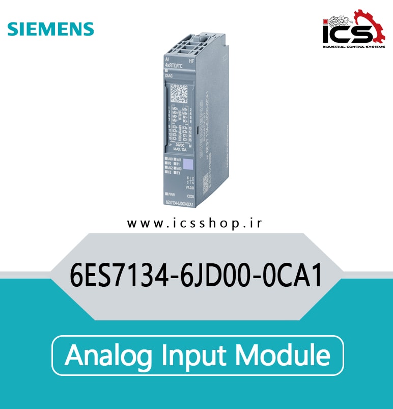
Analog Input Module 6ES7134-6JD00-0CA1
SIMATIC SIEMENS ET 200SP, Analog input module , AI 4xRTD/TC High Feature, suitable for BU type A0, A1, Color code CC00, channel diagnostics, 16 bit, +/-0.1%, 2-/3-/4-wire
| SIEMENS | |
General information |
|
| Product type designation | AI 4x RTD/TC 2/3/4-wire HF, PU 1 |
| HW functional status | From FS08 |
| Firmware version
● FW update possible |
Yes |
| usable BaseUnits | BU type A0, A1 |
| Color code for module-specific color identification plate | CC00 |
| Product function | |
| ● I&M data | Yes; I&M0 to I&M3 |
| ● Adjustment of measuring range | Yes |
| Engineering with | |
| ● STEP 7 TIA Portal configurable/integrated as of version | V14 |
| ● STEP 7 configurable/integrated as of version | V5.6 |
| ● PCS 7 configurable/integrated as of version | V8.1 SP1 |
| ● PROFIBUS as of GSD version/GSD revision | One GSD file each, Revision 3 and 5 and higher |
| ● PROFINET as of GSD version/GSD revision | GSDML V2.3 |
| Operating mode | |
| ● Oversampling | No
No |
| ● MSI | |
| CiR – Configuration in RUN | |
| Reparameterization possible in RUN | Yes |
| Calibration possible in RUN | Yes |
| Supply voltage | |
| Rated value (DC) | 24 V |
| permissible range, lower limit (DC) | 19.2 V |
| permissible range, upper limit (DC) | 28.8 V |
| Reverse polarity protection | Yes |
| Input current | |
| Current consumption, max. | 35 mA |
| Power loss | |
| Power loss, typ. | 0.75 W |
Address area |
|
| Address space per module | |
| ● Address space per module, max. | 8 byte; + 1 byte for QI information |
| Hardware configuration | |
| Automatic encoding | Yes |
| ● Mechanical coding element | Yes |
| Selection of BaseUnit for connection variants | |
| ● 2-wire connection | BU type A0, A1 |
| ● 3-wire connection | BU type A0, A1 |
Analog inputs |
|
| Number of analog inputs | 4 |
| permissible input voltage for voltage input (destruction limit), max. | 30 V |
| Cycle time (all channels), min. | Sum of the basic conversion times and additional processing times (depending on the parameterization of the active channels); for line compensation in case of a three-wire connection, an additional cycle is necessary |
| Technical unit for temperature measurement adjustable | Yes; °C/°F/K |
| Input ranges (rated values), voltages | |
| ● -1 V to +1 V | Yes; 16 bit incl. sign |
| ● Input resistance (-1 V to +1 V) | 1 MΩ |
| ● -250 mV to +250 mV | Yes; 16 bit incl. sign |
| ● Input resistance (-250 mV to +250 mV) | 1 MΩ |
| ● -50 mV to +50 mV | Yes; 16 bit incl. sign
1 MΩ |
| ● Input resistance (-50 mV to +50 mV) |
| ● Input resistance (Ni 500) | 1 MΩ
Yes; 16 bit incl. sign |
| ● Pt 100 | |
| ● Input resistance (Pt 100) | 1 MΩ |
| ● Pt 1000 | Yes; 16 bit incl. sign |
| ● Input resistance (Pt 1000) | 1 MΩ |
| ● Pt 200 | Yes; 16 bit incl. sign |
| ● Input resistance (Pt 200) | 1 MΩ |
| ● Pt 500 | Yes; 16 bit incl. sign |
| ● Input resistance (Pt 500) | 1 MΩ |
| Input ranges (rated values), resistors | |
| ● 0 to 150 ohms | Yes; 15 bit |
| ● Input resistance (0 to 150 ohms) | 1 MΩ |
| ● 0 to 300 ohms | Yes; 15 bit |
| ● Input resistance (0 to 300 ohms) | 1 MΩ |
| ● 0 to 600 ohms | Yes; 15 bit |
| ● Input resistance (0 to 600 ohms) | 1 MΩ |
| ● 0 to 3000 ohms | Yes; 15 bit |
| ● Input resistance (0 to 3000 ohms) | 1 MΩ |
| ● 0 to 6000 ohms | Yes; 15 bit |
| ● Input resistance (0 to 6000 ohms) | 1 MΩ |
| ● PTC | Yes; 15 bit |
| ● Input resistance (PTC) | 1 MΩ |
| Thermocouple (TC) | |
| Temperature compensation | |
| — parameterizable | Yes |
| — Reference channel of the module | Yes |
| — internal comparison point | Yes; with BaseUnit type A1 |
| — Reference channel of the group | Yes |
| — Number of reference channel groups | 4; Group 0 to 3 |
| — fixed reference temperature | Yes |
Cable length |
|
| ● shielded, max. | 200 m; 50 m with thermocouples |
| Analog value generation for the inputs | |
| Measurement principle | integrating (Sigma-Delta) |
| Integration and conversion time/resolution per channel | |
| ● Resolution with overrange (bit including sign), max. | 16 bit |
| ● Integration time, parameterizable | Yes |
| ● Basic conversion time, including integration time (ms) |
| — additional processing time for wire-break check | 2 ms; In the ranges resistance thermometers, resistors and thermocouples
2 ms; for 3/4 wire transducer (resistance thermometer and resistor) |
| — additional power line wire-break check | |
| ● Interference voltage suppression for interference frequency f1 in Hz | 16.6 / 50 / 60 Hz |
| ● Conversion time (per channel) | 180 / 60 / 50 ms |
| Smoothing of measured values | |
| ● Number of smoothing levels | 4; None; 4/8/16 times |
| ● parameterizable | Yes |
| Encoder | |
| Connection of signal encoders | |
| ● for voltage measurement | Yes |
| ● for resistance measurement with two-wire connection | Yes |
| ● for resistance measurement with three-wire connection | Yes |
| ● for resistance measurement with four-wire connection | Yes |
| Errors/accuracies | |
| Linearity error (relative to input range), (+/-) | 0.01 %; ±0.1 % for resistance thermometers and resistance |
| Temperature error (relative to input range), (+/-) | 0.0009 %/K; ±0.005 % / K at thermocouple |
| Crosstalk between the inputs, min. | -50 dB |
| Repeat accuracy in steady state at 25 °C (relative to input range), (+/-) | 0.05 % |
| Operational error limit in overall temperature range | |
| ● Voltage, relative to input range, (+/-) | 0.1 % |
| ● Resistance, relative to input range, (+/-) | 0.1 % |
| Basic error limit (operational limit at 25 °C) | |
| ● Voltage, relative to input range, (+/-) | 0.05 % |
| ● Resistance, relative to input range, (+/-) | 0.05 % |
| Interference voltage suppression for f = n x (f1 +/- 1 %), f1 = interference frequency | |
| ● Series mode interference (peak value of interference < rated value of input range), min. | 70 dB |
| ● Common mode voltage, max. | 10 V |
| ● Common mode interference, min. | 90 dB |
Isochronous mode |
|
| Isochronous operation (application synchronized up to terminal) | No |
| Interrupts/diagnostics/status information | |
| Diagnostics function | Yes |
| Alarms | |
| ● Diagnostic alarm | Yes
Yes; two upper and two lower limit values in each case |
| ● Limit value alarm | |
| Diagnostic messages | |
| ● Monitoring the supply voltage | Yes |
| ● Wire-break | Yes; channel by channel |
| ● Group error | Yes |
| ● Overflow/underflow | Yes; channel by channel |
| Diagnostics indication LED | |
| ● Monitoring of the supply voltage (PWR-LED) | Yes; Green PWR LED |
| ● Channel status display | Yes; Green LED |
| ● for channel diagnostics | Yes; Red LED |
| ● for module diagnostics | Yes; green/red DIAG LED |
| Potential separation | |
| Potential separation channels | |
| ● between the channels | No |
| ● between the channels and backplane bus | Yes |
| ● between the channels and the power supply of the electronics | Yes |
Isolation |
|
| Isolation tested with | 707 V DC (type test) |
| Ambient conditions | |
| Ambient temperature during operation | |
| ● horizontal installation, min. | -30 °C |
| ● horizontal installation, max. | 60 °C |
| ● vertical installation, min. | -30 °C |
| ● vertical installation, max. | 50 °C |
| Altitude during operation relating to sea level | |
| ● Installation altitude above sea level, max. | 5 000 m; Restrictions for installation altitudes > 2 000 m, see manual |
| Dimensions | |
| Width | 15 mm |
| Height | 73 mm |
| Depth | 58 mm |
| last modified: | 01/20/2020 |
SIEMENS Analog Input Module 6ES7134-6JD00-0CA1
Be the first to review “Analog Input Module 6ES7134-6JD00-0CA1”
-

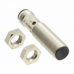
سنسور القایی OMRON E2B-M12KS04-M1-B1 امرن
تماس بگیرید◀️ نوع محصول : سنسور امرن / القایی / مجاورتی ◀️ قطر سنسور : استوانه ای قطر 12 ◀️ خروجی سنسور : PNP NO -
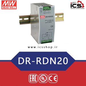
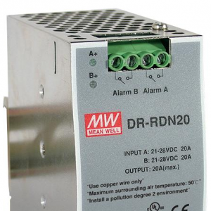
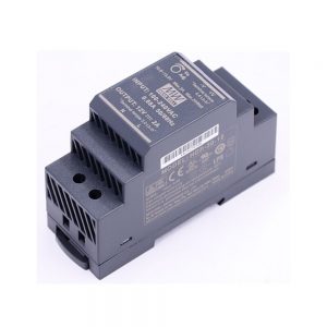
ماژول DR-RDN20
0 تومانماژول DR-RDN20 جزء سری ماژول های ریلی مین ول محسوب می شود. مناسب برای استفاده دو منبع تغذیه به صورت همزمان دارای کنتاکت سیگنال رله ای با نشانگر LED . مورد استفاده برای سیستم های 24 ولت .استاندارد نصب بروی تابلوهای صنعتی ts35-7.5- 15 . ماژول بدون فن ساخته شده و به وسیله ی انتقال حرارت از طریق هوا عمل خنک کننده گی صورت می گیرد . -
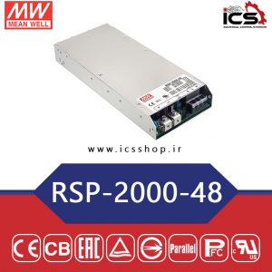
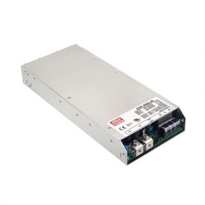
منبع تغذیه 48 ولت 42 آمپر مین ول
0 تومانمنبع تغذیه 48 ولت 42 آمپر مین ول سری 48 RSP 2000 با توان 2016 وات واقعی در خروجی اندازه گیری شده است. یک از قابلیت های برجسته ی این سری از منبع تغذیه ها مین ول امکان موازی کردن تا چهار دستگاه با یک دیگر است به طوری که بتوان در خروجی با همان ولتاژ 48 ولت، جریان را حداکثر تا 168 آمپر افزایش دارد. -
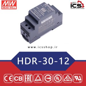
منبع تغذیه 12 ولت 2 آمپر مین ول
0 تومانمنبع تغذیه 12 ولت 2 آمپر مین ول (HDR-30-12) با توان 24 وات واقعی و تحویلی به مصرف کننده ساخته شده است. این منبع تغذیه جزء محصولات ریلی شرکت مین ول محسوب می شود. راندمان این منبع تغذیه به عدد بالای 88% می رسد که در نوع خود بسیار خوب و کارآمد است. تلفات توان در این منبع تغذیه بسیار کم و در حدود 0.3 وات در حالت بی باری… -
اینورتر 3 کیلووات اشنایدر سری ATV310 ورودی سه فاز
تماس بگیرید[gravityform id="9" title="true" description="true"]


-
Analog Input Module 6ES7134-6GF00-0AA1
تماس بگیریدSIMATIC ET 200SP, Analog input module , AI 8XI 2-/4-wire Basic, suitable for BU type A0, A1, Color code CC01, Module diagnostics, 16 bit -
Push-in terminals 6ES7193-6BP20-0DA0
تماس بگیریدSIMATIC ET 200SP, BaseUnit BU15-P16+A10+2D, BU type A0, Push-in terminals, with 10 AUX terminals, New load group, WxH: 15 mmx141 mm -
Digital Input Module 6ES7131-6BH00-0BA0
تماس بگیرید*** Spare part *** SIMATIC ET 200SP, digital input module, DI 16X 24 V DC Standard, suitable for BU type A0, color code CC00, module diagnostics -
Push-in terminals 6ES7193-6BP00-0DA1
تماس بگیریدSIMATIC ET 200SP, BaseUnit BU15-P16+A0+2D/T, BU type A1, Push-in terminals, without AUX terminals, New load group, WxH: 15x 117 mm, with temperature acquisition -
PROFINET Interface 6ES7155-6AU00-0CN0
تماس بگیرید*** Spare part *** SIMATIC ET 200SP, PROFINET interface module IM 155-6PN High Feature max. 64 I/O modules, 0.25 ms isochronous mode Multi-hotswap, incl. server module -

Memory Cards 6ES7954-8LF02-0AA0
تماس بگیرید***Spare part*** SIMATIC S7, memory cards for S7-1x 00 CPU/SINAMICS, 3, 3V Flash, 24 MByte -
SIEMENS Rail 6ES7590-1AB60-0AA0
تماس بگیریدSIMATIC S7-1500, mounting rail 160 mm (approx. 6.3 inch); incl. grounding screw, integrated DIN rail for mounting of incidentals such as terminals, automatic circuit breakers and relays -
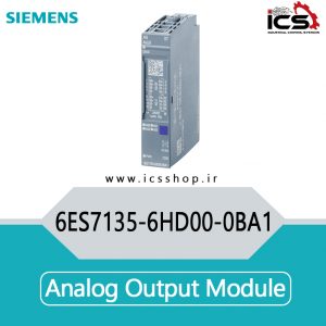
Analog Output Module 6ES7135-6HD00-0BA1
تماس بگیریدSIMATIC ET 200SP, Analog output module, AQ 4XU/I Standard, suitable for BU type A0, A1, Color code CC00, Module diagnostics, 16 bit, +/-0.3% -
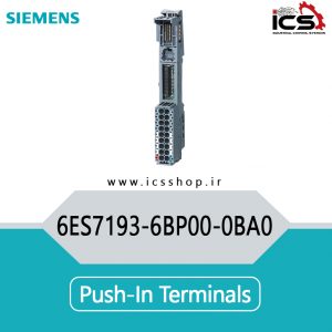
Push-in terminals 6ES7193-6BP00-0BA0
تماس بگیریدSIMATIC ET 200SP, BaseUnit BU15-P16+A0+2B, BU type A0, Push-in terminals, without AUX terminals, bridged to the left, WxH: 15x 117 mm -
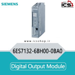
Digital Output Module 6ES7132-6BH00-0BA0
تماس بگیرید*** Spare part *** SIMATIC ET 200SP, Digital Output Module , DQ 16x 24VDC/0.5A Standard, suitable for BU type A0, Color code CC00, module diagnostics -
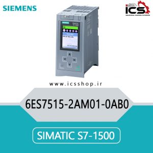
S7-1500 SIEMENS 6ES7515-2AM01-0AB0
تماس بگیریدSIMATIC S7-1500, CPU 1515-2 PN, Central processing unit with work memory 500 KB for Program and 3 MB for data, 1st interface: PROFINET IRT with 2-port switch, 2nd interface: PROFINET RT, 30 ns bit performance, SIMATIC Memory Card required -
پی ال سی لوگو LOGO 8 SIEMENS
شروع از : 7,100,000 تومانPLC ﻣﺨﻔﻒ ﻋﺒﺎرت Controller Logic Programmable و در واﻗﻊ ﻧﻮﻋﯽ ﮐﺎﻣﭙﯿﻮﺗﺮ ﺑﺮﻧﺎﻣﻪ ﭘﺬﯾﺮ ﺟﻬﺖ ﮐﻨﺘﺮل ﺳﯿﺴﺘﻢ ﻫﺎ و ﭘﺮوﺳﻪ ﻫﺎي ﺻﻨﻌﺘﯽ ﻣﯽ ﺑﺎﺷﺪ . ﻇﻬﻮر PLC در اﺑﺘﺪا ﺗﺤﻮل ﻋﻈﯿﻤﯽ را در ﺻﻨﻌﺖ ﭘﯿﺶ آورد و از آن ﭘﺲ ﺑﺎ ﺳﺮﻋﺖ ﺳﺮﺳﺎم آوري ﮐﻨﺘﺮل ﻓﺮآﯾﻨﺪ ﻫﺎي ﺻﻨﻌﺘﯽ را رو ﺑﻪ ﺟﻠﻮ ﺑﺮد ، ﺗﺎ ﺟﺎﯾﯽ ﮐﻪ اﻣﺮوزه ﺗﻘﺮﯾبا در ﺗﻤﺎم ﭘﺎﻻﯾﺸﮕﺎه ﻫﺎ ، ﭘﺘﺮوﺷﯿﻤﯽ ﻫﺎ ، ﮐﺎرﺧﺎﻧﺠﺎت ﺗﻮﻟﯿﺪي ، ﮐﺎرﮔﺎه…


Reviews
There are no reviews yet.